Key Takeaways
- Aerospace CNC inspection failures create costly delays, audits and production holds, so a structured workflow protects flight-critical programs.
- AS9100D and ITAR compliance require documented traceability from incoming material verification through final certificate of conformance release.
- Precision Advanced Manufacturing integrates multi-axis CNC machining, CMM and optical metrology, NDT and full documentation under one roof to reduce supplier qualification burden.
- The 8-step workflow covers incoming verification, AS9102 first-article inspection, in-process probing with SPC, CMM and optical decision points, NDT selection, surface-finish checks, traceability packaging and CoC release.
- Request a quote at Precision Advanced Manufacturing to align inspection methods and documentation with specific aerospace program requirements.
Inspection Risk in Aerospace CNC Programs
Nonconforming parts create costs that extend well beyond scrap. Integration delays, rework labor, expedited logistics and failed customer audits compound quickly on mission-critical programs. Environmental factors increase the risk further. NIST research on machine tool metrology indicates that thermal drift alone can shift dimensions over a long machining cycle in an uncontrolled shop floor environment, so environmental controls become a baseline requirement rather than a preference.
Compliance failures under AS9100D and ITAR carry additional consequences. AS9100D-certified suppliers must implement configuration management, risk management and first article inspection protocols beyond ISO 9001:2015 baseline requirements. Suppliers without documented, standards-driven inspection lifecycles expose customers to audit findings, delivery holds and program risk.
A structured 8-step inspection workflow addresses these risks from incoming material through final certificate of conformance release. Implementing this workflow requires integrated capabilities that connect machining, metrology and quality documentation.
Precision Advanced Manufacturing Integrated Inspection Capability
Precision Advanced Manufacturing consolidates multi-axis CNC machining, precision fabrication and certified quality systems at facilities in California and Texas. Inspection capabilities include temperature-controlled CMM measurement, in-process probing, surface-finish verification, ballooned-drawing workflows and full material and process traceability. Every deliverable is backed by AS9100D, ISO 9001:2015 and ITAR-registered quality systems designed for flight-critical programs.
Request a quote to discuss inspection and documentation requirements for an active program.
Step 1: Incoming Material Verification and Traceability
Aerospace suppliers must maintain material certifications that trace chemistry, mechanical properties and processing history to specific heat lots to satisfy AS9100D traceability requirements. At incoming, every material batch is verified against the purchase order, engineering drawing and applicable material specification. Heat and lot numbers are recorded and linked to the job traveler, which establishes the traceability chain that carries through to the final certificate of conformance.
Under AS9100D, traceability requirements include material certification and heat and lot linkage, batch and serial identification with controlled labeling, record linkage through outsourced processes such as plating and preservation of records for the required retention period. Any material that cannot be verified to these requirements is quarantined before production begins.
Step 2: First-Article Inspection to AS9102 Rev C
Ballooned drawings provide the backbone for AS9102 reporting. Every FAIR must include a ballooned drawing that uniquely identifies each design characteristic for recording in Form 3. Partial FAI is triggered by manufacturing process, location, tooling or equipment changes, which means any modification to how the part is produced. When the part design changes instead of the manufacturing method, delta FAI applies and limits reinspection to the affected characteristics. AS9102 Rev C clarifies that a lapse in production, commonly defined as two years, requires reassessment of whether a new or partial FAI is needed. A change in the numerical control program or translation to another media directly triggers a requirement for a new or partial FAI.
AS9102 Rev C strengthens configuration control by requiring FAIRs to be tied to a specific drawing or model revision, with later delta or partial FAIs clearly referencing prior FAIRs and the changes that triggered them. This linkage preserves a clear verification history across the product lifecycle.
Step 3: In-Process Probing with SPC for Stable Production
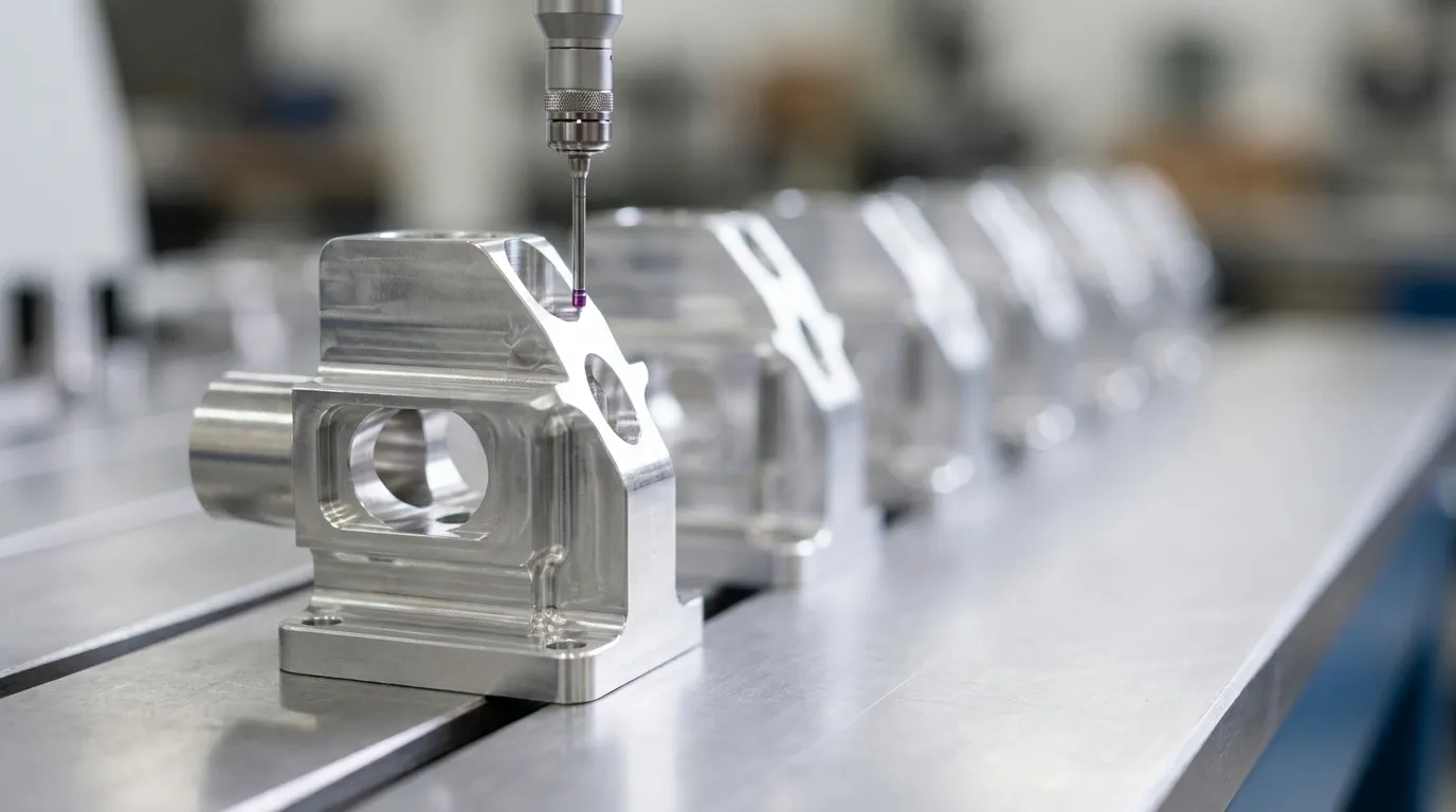
On-machine inspection uses a probe mounted in the CNC machine spindle or turret to measure part dimensions directly on the machine before, during or after machining without removing the part from the fixture. During machining, the probe checks features and automatically adjusts tool offsets to account for temperature drift, tool wear or material variation.
Statistical process control allows CNC shops to maintain tight tolerances across entire production runs by focusing control effort on critical features. SPC charts on key diameters track process stability and support trend-based offset corrections before deviations become nonconformances.
In-process probing complements, but does not replace, independent CMM verification. For aerospace CNC machining under AS9100D, on-machine inspection data alone does not satisfy audit requirements, and customers require traceable CMM reports as formal evidence of conformance. In-process probing reduces CMM sampling frequency by catching most errors first, which preserves CMM capacity for final verification and compliance documentation.
Step 4: CMM and Optical Metrology Selection
Contact CMM measurement remains the standard for tight-tolerance aerospace features with defined datum reference frames. CMM performance in regulated industries must comply with ISO 10360 acceptance and reverification tests, with ASME B89.4.10360 applying in the United States. CMM systems used in aerospace inspection achieve measuring accuracy in the low-micrometer range and are used for open-setup and CAD-aligned inspection under ASME Y14.5. Temperature and humidity-controlled labs eliminate environmental variation and support consistent measurement results.
Optical and laser scanning metrology address geometries where tactile probing is impractical. Portable 3D laser scanners from manufacturers such as Hexagon achieve metrology-grade accuracy suitable for aerospace applications such as jet engine turbine blades where only minimal tolerances are permissible. Blue laser technology enables stable scanning of reflective, polished metals, chrome, carbon fiber and dark surfaces without surface treatment or spray preparation.
The selection between CMM and optical metrology depends on feature type, tolerance class and audit requirements. Contact CMM is preferred for prismatic features, tight GD&T callouts and formal FAIR documentation. Optical scanning is preferred for complex freeform surfaces, large structural assemblies and reverse engineering workflows where full-field data density is required. Both methods require calibration traceability to national standards and documented measurement uncertainty.
Step 5: NDT Technique Selection for Flight-Critical Parts
Critical aerospace components often require ultrasonic, radiographic or magnetic particle inspection in addition to material certifications to meet AS9100D quality standards. NDT method selection depends on material type, feature geometry and the defect types of concern.
Ultrasonic testing detects subsurface discontinuities in metallic and composite structures and is widely applied to forgings, castings and thick-section machined components. Radiographic testing provides volumetric inspection for internal voids, porosity and inclusions, and is common for castings and weldments. Dye-penetrant inspection reveals surface-breaking cracks and is applicable to nonporous metals and some composites. Magnetic particle inspection detects surface and near-surface discontinuities in ferromagnetic materials and is used for steel and iron alloy components.
NDT personnel qualification and method selection for aerospace components are governed by NAS 410 and applicable ISO standards. Special process suppliers performing NDT must be approved per purchase order requirements. Use of unapproved processors will cause FAI rejection under major OEM quality requirements.
Step 6: Surface-Finish Verification for Performance
Surface finish directly affects fatigue life, sealing performance and coating adhesion on flight-critical parts. Ra measurement using contact profilometers or optical profilometers verifies that machined surfaces meet drawing callouts. 3D optical profilometers provide surface-finish measurement with accuracy in the low-micrometer range, and they support both Ra and more complex surface texture parameters where specified.
All surface-finish measurements must be performed in temperature and humidity-controlled labs to align with the controlled environment used for dimensional inspection. Results are recorded in the inspection report and linked to the part serial or lot number for full traceability.
Step 7: Building the Documentation and Traceability Package
Essential aerospace inspection documentation under AS9100D includes AS9102 first-article inspection reports, the material certifications established at incoming, special process certifications, dimensional inspection reports, SPC charts and certificates of conformance. Process travelers record each manufacturing operation, operator, inspection result and date to enable full traceability documentation.
ITAR-controlled programs require additional controls on data access, record storage and export documentation. Every document in the traceability package is tied to a specific part number, drawing revision and serial or lot number, which creates an auditable chain from raw material to shipment. AS9102 Rev C requires that partial and delta FAIs maintain traceable linkage to the baseline full FAI so the product verification history remains transparent and auditable.
Step 8: Certificate of Conformance Release for Shipment
The certificate of conformance is the final gate before shipment. It declares that the delivered parts conform to all applicable drawing, specification and purchase order requirements. The CoC references the FAIR, material certifications, special process certifications, dimensional inspection reports and any applicable NDT records.
A complete documentation package reduces the customer incoming inspection burden and supports first-article acceptance without additional verification cycles. Comprehensive inspection reports stored and available for audit provide traceability documentation aligned with AS9100D and ITAR compliance, which enables customers to accept parts directly into their quality records.
Request a quote and receive a tailored plan covering inspection methods, documentation deliverables and production strategy for a specific program.
Frequently Asked Questions
AS9102 Rev C Triggers for Full, Partial and Delta FAI
AS9102 Rev C requires a full FAI for any new part number and covers all design characteristics on the drawing or model. Partial FAI is triggered by changes to manufacturing process, location, tooling or equipment. Delta FAI applies when an engineering change affects only specific characteristics. Additional triggers include changes to numerical control programs or media translation, corrective actions to complete a prior FAI, adverse events affecting production and production lapses of two years or more. Organizations maintain documented criteria in the quality management system for classifying each trigger and demonstrating that the scope of the FAI matches the impacted characteristics. All partial and delta FAIs reference the prior completed full FAI and any intervening partial FAIRs to maintain a transparent verification history.
Comparing CMM and Optical Metrology for Complex Geometries
Contact CMM measurement is the established standard for prismatic features, tight geometric dimensioning and tolerancing callouts and formal first-article inspection documentation. CMMs operating in temperature-controlled environments and calibrated to ISO 10360 provide the measurement traceability required for AS9100D audit evidence. Optical and laser scanning metrology suit complex freeform surfaces, large structural assemblies and parts where tactile probing is impractical because of feature accessibility or surface fragility. Portable laser scanners capture full-field geometry at high point density, which enables rapid comparison against CAD models. Many aerospace programs use the two methods together, with CMM for critical tolerance verification and formal documentation and optical scanning for geometric deviation mapping and process validation on complex surfaces.
Using In-Process Probing Versus Independent CMM Verification
In-process probing on the CNC machine supports datum verification, tool offset correction and mid-cycle dimensional checks that prevent defects from propagating through a production run. It supports closed-loop process control and reduces the rate at which parts require full CMM inspection. However, in-process probing is subject to the same geometric errors as the machine itself, so a machine axis error will appear correct to the probe. For tight-tolerance or safety-critical aerospace features, independent CMM verification in a controlled environment is required. Under AS9100D, traceable CMM reports provide the formal evidence of conformance for audit purposes. In-process probing stabilizes the process, and CMM verification supplies the documented proof.
NDT Methods for Post-Machining Aerospace CNC Components
NDT requirements are determined by the engineering drawing, material specification, purchase order and applicable customer or regulatory requirements. Ultrasonic testing is commonly specified for subsurface discontinuity detection in metallic forgings, castings and thick-section machined parts. Radiographic testing provides volumetric inspection for internal voids and inclusions in castings and weldments. Dye-penetrant inspection is used for surface-breaking crack detection on nonporous metals and some composites. Magnetic particle inspection applies to ferromagnetic materials for surface and near-surface discontinuity detection. Personnel qualification and method application are governed by NAS 410 and applicable ISO standards. Approved special process suppliers perform NDT, and results are documented and included in the traceability package delivered with the parts.
Conclusion: A Connected 8-Step Inspection Lifecycle
The 8-step inspection lifecycle, from incoming material verification through CoC release, provides the documented, traceable evidence that flight-critical programs require. Each step builds on the last and creates an auditable chain that supports AS9102 FAI, AS9100D compliance and ITAR controls without gaps.
Precision Advanced Manufacturing delivers this workflow from a single facility with multi-axis CNC machining, certified inspection and complete documentation under AS9100D, ISO 9001:2015 and ITAR-registered quality systems. Scalable multi-shift capacity supports both prototype validation and full-rate production without supplier transitions or documentation restarts.
Request a quote to connect with Precision Advanced Manufacturing aerospace manufacturing specialists and define inspection, documentation and production requirements for a mission-critical program.
